
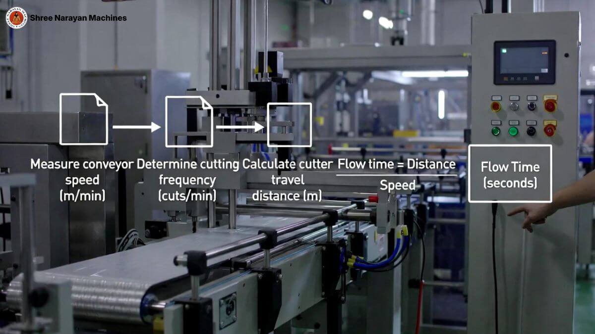
In horizontal flow wrapping (HFFS) the cutter must operate in perfect sync with the film feed and infeed conveyor. Cutter flow time (also called cutter cycle time or dwell time) is the time window during which the cutter engages, seals, and separates a pack while the product is stationary (intermittent) or while the cutter moves with the product (flying shear).
Key variables and formula
Important variables
- = product pitch (distance between product centers) in mm.
- = film linear speed (mm/s).
- = target packs per minute (ppm).
- = cutter cycle time (s) — the value to calculate.
- = cutter dwell or engagement time (s) — mechanical requirement for seal formation.
Basic relationships
- Packs per second .
- Product pitch .
Cutter cycle time formula
Dwell requirement
where is the minimum seal time determined by film and sealer temperature/pressure.
Worked example (practical)
- Target: 600 ppm (common mid‑high speed line).
- Packs per second = packs/s.
- Cutter cycle time s (100 ms).
- If the sealer requires 30 ms to form a reliable seal, set cutter dwell to 35–40 ms to allow margin. Ensure cutter actuation and blade travel fit within the remaining 60–65 ms for acceleration/deceleration or flying shear motion.
Table — quick parameter checklist
| Parameter | Symbol | Typical value | Why it matters |
|---|---|---|---|
| Product pitch | P | 50–200 mm | Determines film advance per cycle |
| Target speed | N | 100–2000 ppm | Sets cutter cycle time |
| Cutter cycle time | T_c | s | Synchronization baseline |
| Dwell time | t_d | 20–100 ms | Seal integrity requirement |
| Film speed | V_f | mm/s | Must match conveyor & cutter timing |
Practical tips to reduce scrap and improve timing
- Measure actual film slip with a tachometer; adjust in PLC to match theoretical pitch.
- Use servo‑driven cutters for precise acceleration profiles and repeatable .
- Validate seal time experimentally: run a seal‑strength test at different and temperatures.
- Account for mechanical lag: include actuator response time in budget.
- Implement closed‑loop feedback (encoder on film and cutter) to auto‑correct drift.
Troubleshooting checklist
- Cutter misses sync: check encoder wiring and PLC phase alignment.
- Weak seals: increase or sealer temperature; check film compatibility.
- Excessive scrap at high speed: reduce acceleration, use flying shear, or increase lanes.
Conclusion
Calculating cutter flow time is a mix of simple timing math and empirical validation. Start with , allocate safe dwell for sealing, and validate on the line with real film and product. For a tailored calculation, share product dimensions, target ppm, and film type, and I’ll produce a step‑by‑step timing sheet and PLC parameter set.